Electronic Firing System Features 

RISI manufactures a complete line of EBW and EFI Firing Systems. Most systems are designed to allow remote arming and firing and to separate high voltage from the operator. These systems provide users with options to accommodate most firing applications with off-the-shelf products. Click on the Fire Set titles below for more features and specifications.


FIRING SYSTEM DEPOYMENT

PM-100

  • For use with conventional blasting systems to provide proper EBW firing pulse
  • Uses RISI twin lead blasting wire
  • Distance from charge: Up to100 feet using twin lead or up to 300 feet using type ‘C” cable

FS-17

  • Battery powered
  • Separate high voltage module
  • External control and synchronization
  • High Voltage meter
  • Coaxial output
  • Up to 2000 feet from charge

FS-500

  • Ultra-Low Cost Firing System
  • Battery powered
  • Separate high voltage module
  • Distance from Charge: Up to 10,000 feet

FS-43

  • AC powered
  • Separate high voltage module
  • External control and synchronization
  • High Voltage meter
  • Coaxial output
  • Up to 10,000 feet from charge

PX-1

  • A low cost disposable downhole fireset

EFI Test Module​

  • A tester for investigating EFI performance
  • Designed to detonate EFI's
  • Flat cable connection
  • Requires separate high voltage power supply
  • Close coupled for EFI functioning

​Firing System Development ​D​own​load as PDF

Typical deployment of a system u​sing a separate control unit and firing module


Typical deployment of a system using an integrated control unit and firing module
Caution:While EBW and EFI Initiators are inherently less susceptible to accidental detonation during handling and set-up than devices containing primary explosives, electrical and electronic firing systems are sensitive to transient electrical energies which could cause premature triggering or firing. The blasting area must be clear of personnel and equipment before the detonator leads are connected to any RISI Firing System. Only approved RISI Firing Systems should ever be used to initiate or detonate any explosive product manufactured and authorized for sale by RISI.

​PM-100 Power Multiplier ​

P/N 188-7387​ - D​ownload as PDF


Installation
1. Place the RISI PM-100 as close to the required blasting machine as possible.

2. Connect the OUTPUT of the blaster to the INPUT of the PM-100 using RISI twin lead cable, P/N 167-8559.

3. Connect the EBW detonator to the OUTPUT of the PM-100 using a maximum of 100 ft. of RISI twin lead cable, P/N 167-8559, or a maximum of 300 ft. of RISI coaxial cable, P/N 167-2669.
Required Machine Output

10 Joules, minimum
350 volts, minimum

PM-100 Specification
Size: 3" X 4" X 5"
Weight: 6 pounds (approx.)
Output: Sufficient to function a RISI EBW
Detonator when properly installed.

Caution: While EBW and EFI Initiators are inherently less susceptible to accidental detonation during handling and set-up than devices containing primary explosives, electrical and electronic firing systems are sensitive to transient electrical energies which could cause premature triggering or firing. The blasting area must be clear of personnel and equipment before the detonator leads are connected to any RISI Firing System. Only approved RISI Firing Systems should ever be used to initiate or detonate any explosive product manufactured and authorized for sale by RISI.​

​FS-17 Firing System​


DESCRIPTION
 The RISI FS-17 EBW firing system is designed for field firings where (1) there is no 110 or 220 VAC power available, (2) where the actual module voltage must be monitored and (3) where instantaneous firing or external triggering is required. The system consists of a Control Unit (P/N 167-8917) and a Firing Module (P/N 167-8371). The system also includes a battery voltage meter, keyed arm switch and coaxial output connector on the module.

 
Design and Specifications
Input Energy
  • Battery supply for a minimum of 50 firings.
  • Built-in battery charger for 110 VAC
  • (220 available)
Output Energy
  • 4000 volt pulse with 1500 amperes peak current into low resistance load (8.0 joules).
Circuit
  • Regulated DC battery power supply in Control Unit.
  • DC to DC converter with high voltage energy storage capacitor in firing module
  • Triggered gap for instantaneous firing (typically less than 10 microseconds)
  • Meters in Control Unit to monitor module capacitor voltage and battery voltage
  • External or internal trigger monitor
Control Unit Input Connection
  • U.S. Type, 3 pin plug for 110 VAC battery recharging
  • (Special plug for 220 VAC if required)
  • Safety interlock and Key Arm Switch to arm
  • Meter to indicate module arm voltage & discharge rate
  • Five-pin connector to module
  • Six-pin connector for accessory connection for ‘Pulse Out’
  • External trigger pulse out
  • External switch closure
  • External breakwire
  • Automatic trigger
  • Meter to indicate battery voltage
  • External dimensions: 6”x7”x9”
Control Unit to Module Connection
  • Requires 3 Pair Shielded Cable with ground used as a shield
  • Maximum 2,000 feet of 20 gauge wire
Module
  • Five pin connector for connection from Control Unit
  • Safety Interlock Connector
  • Reynolds Type 31 Coaxial output connector
Module to Detonator Connection
  • Maximum 100 feet twin lead blasting wire (P/N 167-8559)
  • Maximum 300 feet Type “C” high voltage coaxial cable (P/N 167-2669)
WARNING
  • MAXIMUM Firing RATE: 1 Shot every 5 minutes- Applies to all arm/fire events


The purpose of the FS-17 Control Unit is to provide low voltage electrical energy to the Firing Module and to ensure a safe and reliable operation sequence for the firing of EBW detonators.
 
The output from the Control Unit to the Firing Module is 40 volts when the batteries are fully charged. This output occurs when the “Arm” switch is held in the “Arm” position and the shorting plug is mated into the Control Unit “Safety Interlock” connection. When the “Test” switch is pulled, the battery voltage will be displayed on the battery meter. The battery should provide a minimum of 32 volts to properly operate the system. When the system is “armed,” the “Firing Volts” meter will display the high voltage from the Firing Module. The high voltage must be at least 3500 volts before firing is initiated.
 
The purpose of the FS-17 Firing Module is to provide a significant amount of flexibility to this EBW detonator firing system. Since the firing pulse to function the EBW detonator must be applied with a rapid pulse rate of rise, the Firing Module must be placed relatively close to the detonator. By being able to separate the Firing Module from the Control Unit, the operator can perform the detonation at extended distances as required by the size and characteristics of the main explosive charge.
 
The input voltage to charge the Firing Module must be between 32 and 40 volts. This low voltage input enables the Module circuitry to charge a one microfarad capacitor. When this capacitor reaches 4000 volts, the Firing Module is ready to be fired. Triggering of the triggered spark gap occurs by applying a 30 volt pulse to the Module. This discharges the one microfarad capacitor into the coaxial output connector which, if properly connected, will fire the EBW detonator. Detonation will occur in less than 10 microseconds from the time that the 30 volt trigger pulse is applied to the Module. 
 
By mating the shorting plug to the “Discharge” connector, the energy storage capacitor is completely and immedi-ately discharged thus precluding inadvertent arming of the Firing Module and detonation of the EBW detonator.
Caution: While EBW and EFI Initiators are inherently less susceptible to accidental detonation during handling and set-up than devices containing primary explosives, electrical and electronic firing systems are sensitive to transient electrical energies which could cause premature triggering or firing. The blasting area must be clear of personnel and equipment before the detonator leads are connected to any RISI Firing System. Only approved RISI Firing Systems should ever be used to initiate or detonate any explosive product manufactured and authorized for sale by RISI.​

​FS-500 Economy Firing System​ D​o​wnload as PDF


DESCRIPTION
The FS-500 EBW Firing System is designed for field firings. The separate module allows up to 10,000 FT separation from the control unit. A micro controller in the Firing Module(p/n 188-7499) will ONLY allow activation from the FS-500 Control Unit(188-7498). Optional accessory is a pelican case.

Design and Specifications
Input Energy
  • Qty 3, 9 volt Batteries
  • Estimated 250 firings per battery life         

Output Energy

  • 2000 volt pulse with 1500 amperes peak current into low resistance load. (0.75 joules.

Circuit

  • Power Multiplier with high voltage energy.
  • Overvoltage gap
  • Redundant bleed resistors for safety
  • Firing module has a micro controller that requires communication from control unit for activation.

 Module

  • Five-way binding post input terminals matched to control unit
  • Five-way binding post output terminals
  • External Dimensions: 8" X 3" X 1.25"

Control Unit

  • Generates 200 Volts DC
  • Dual Push Button Activation
  • Battery Check Light
  • Continuity Check Light
  • Five-way binding post output terminals
  • External dimensions: 6.5” x 4.5” x 2”

Control Unit to Module Connection

  • Maximum 10,000 feet of 20 gauge wire

Module to Detonator Connection

  • Maximum 25 feet twin lead blasting wire, P/N 167- 8559 or 75 feet maximum Type ‘C’ coaxial cable, P/N 167-2669
WARNING
  • Dry firing without firing cable can damage the unit
  • Max shot to shot firing rate- 5 min. Min
 
Caution: While EBW and EFI Initiators are inherently less susceptible to accidental detonation during handling and set- up than devices containing primary explosives, electrical and electronic firing systems are sensitive to transient electrical energies which could cause premature triggering or firing. The blasting area must be clear of personnel and equipment before the detonator leads are connected to any RISI Firing System. Only approved RISI Firing Systems should ever be used to initiate or detonate any explosive product manufactured and authorized for sale by RISI.

​​​FS-43 Firing System

D​ow​nload as PDF


DESCRIPTION
 The FS-43 EBW Firing System is designed for field firings where the actual module voltage must be monitored and instantaneous firing is required and AC power is available. The separate module allows long distance and remote firings to be performed. The system includes a Control Unit (P/N 188-7238)  and a Firing Module (P/N 188-7096) .

 
Design and Specifications
Input Energy
  • 110 VAC standard
  • 220 VAC availablle
Output Energy

  • 4000 volt pulse with 1500 amperes peak current
    into low resistance load. (8.0 joules)
Circuit
  • DC to DC converter with high voltage energy
  • Triggered gap for instantaneous firing (less than 10 microseconds)
  • Meter in Control Unit to monitor voltage
  • External or manual trigger.
  • Trigger monitor
  • Remote arming
Control Unit Input Connection
  • U.S. Type, 3-pin plug for 110 VAC
Control Unit
  • Safety Interlock Connector
  • Sealed Arm Switch with indicator light
  • Adjustment for long control cables
  • Three-pin plug for 110 VAC
  • Meter to indicate module arm voltage and discharge rate
  • Six-pin connector to module
  • Three-pin connector for remote arm
  • BNC connector for external trigger In and Out
  • Short circuit protected
  • External dimensions: 19” x 5” x 13”
Control Unit to Module Connection
  • Requires 3-pair shielded cable
  • Maximum 10,000 feet of 20 gauge wire
Module
  • Six-pin connector for connection from Control Unit
  • Safety interlock connector
  • Five-way binding post output terminals
Module to Detonator Connection
  • Maximum 100 feet twin lead blasting wire, P/N 167-8559 or 300 feet maximum Type ‘C’ coaxial cable, P/N 167-2669 
WARNING
  • MAXIMUM Firing RATE: 1 Shot every 5 minutes- Applies to all arm/fire events


FS-43 Operation Discussion
The purpose of the FS-43 Control Unit is to provide low voltage electrical energy to the Firing Module and to ensure a safe and reliable operation sequence for the firing of EBW detonators.

The output from the Control Unit to the Firing Module is 40 to 120 volts. This output occurs when the “Arm” switch is held in the “Arm” position and the shorting plug is mated into the Control Unit “Safety Interlock” connection. When the system is armed, the “Firing Volts” meter will read the high voltage from the Firing Module. The “Line Adjust” knob is then used to adjust the firing voltage to 4000 volts before firing is initiated. When the “Fire” button is pressed or an external pulse is applied to the “Accessary” connection, detonation will typically occur within 10 microseconds (10x10 -6). Should the operator wish to abort firing while arming is taking place, simply release the “Arm” switch.

The purpose of the FS-43 Firing Module is to provide a significant amount of flexibility to this EBW detonator firing system. Since the firing pulse to function the EBW detonator must be applied at the proper rate of rise, or frequency, the firing module must be placed relatively close to the detonator. By being able to separate the Firing Module from the control unit, the operator can perform the detonation at extended distances as required by the size and characteristics of the main explosive charge.

The input charge to the Firing Module must be between 32 and 40 volts. This low voltage input is applied to the input connector which charges a one microfarad capacitor. When this capacitor reaches 4000 volts, the Firing Module is ready to be fired. Triggering of the triggered spark gap occurs by applying a 30 volt pulse to the input connector. This discharges the one microfarad capacitor into the yellow terminals which, if properly connected, will fire the EBW detonator. Detonation will occur in less than 10 microseconds from the time that the 30 volt pulse is applied.

By mating the shorting plug to the “Discharge” connector, the energy storage capacitor is completely and immediately discharged thus precluding inadvertent arming of the firing module and detonation of the EBW detonator.
Caution: While EBW and EFI Initiators are inherently less susceptible to accidental detonation during handling and set-up than devices containing primary explosives, electrical and electronic firing systems are sensitive to transient electrical energies which could cause premature triggering or firing. The blasting area must be clear of personnel and equipment before the detonator leads are connected to any RISI Firing System. Only approved RISI Firing Systems should ever be used to initiate or detonate any explosive product manufactured and authorized for sale by RISI.

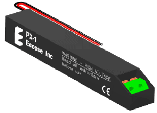
​​Introducing the PX-1 Expendable Fireset

Improved perforating safety should be offered as:
(a) an expensive option.
(b) a standard item.

The need for radio silence during explosives operations is:
(a) very costly to eliminate.
(b) a thing of the past.

During perforating jobs, electric welding and helicopter flights should be:
(a) suspended.
(b) continued as normal.
​​​​​ 
Typical PX-1 output pulse
PX-1 = Pulse eXpendable1
EBW = Exploding Bridge Wire
EFI = Exploding Foil Initiator​​

​Of Course, you'd like to complete all the above statements with option (b), and now you can. Designed and certified to be immune to the stray voltages and RF environment typically found on well sites and offshore platforms, the PX-1 from Ecosse is a low-cost, high performance EBW/EFI fireset that allows normal oilfield operations to continue while perforating and other completion services are being performed.


Radios stay on; communication links are unbroken; helicopter flights continue; construction work is uninterrupted; production is unaffected; the use of sensitive primary explosives is avoided. All of these advantages are available with the PX-1 fireset from Ecosse.

Designed primarily for oilfield applications, the PX-1 generates the high-current pulse needed to initiate EBW and EFI detonators. With features that complement the safety characteristics of these detonators. compact dimensions that allow it to be used in gun systems down to 1-3/8in OD, a low cost that allows it to be discarded after one use, and a temperature rating greater than any other system on the market, the PX-1 is a flexible and affordable tool that will immediately improve your bottom line.​


"The PX-1 firing tool safety features operated as intended to prevent accidental firing due to the effects of RF interference and stray voltages as might typically be found in the oilfield environment. These electrical safety features also successfully provided protection against a direct lightning strike to the wireline. The PX-1 Firing System, therefore, meets its design requirements by allowing perforating operations to be conducted without interrupting radio communications, welding operations, cathodic protection systems, or other potential sources of stray voltages."

 
Quote from certification report by Orion International Technologies Inc

​​
​​ What are EBW and EFI Detonators?
EBW and EFI detonators were originally developed for use in military applications. They need a very fast rising, high-current pulse for successful initiation, such as the output provided by the Ecosse PX-1.

Unlike conventional hot-wire and hot-resistor detonators normally used in oilfield perforating operations, EBW and EFI detonators do not contain sensitive primary explosives such as lead azide.

Why use EBW/EFI?
The greatest advantage of EBW and EFI detonators for oilfield use is the fact that they are extremely insensitive to accidental initiation. They are effectively immune to the Radio Frequency (RF) sources and stray voltages found on well sites and offshore platforms, which means radio transmitter, electric welding and cathodic protection equipment need not be turned off during perforating and other wireline explosives operations.
Which type to use?
EBWs are generally easier to initiate than EFIs, which makes them more tolerant of imperfect wiring methods and allows them to be fired over relatively long lengths of wire. EBWs are also less expensive than EFls, typically costing about the same as conventional hot-wire detonators. Oilfield EBWs are available using RDX and CP explosives, giving them useful temperature ratings of 163°C (325°F) and 204ºC (400ºF) respectively.

EFls are more difficult to initiate than EBWs, and they are typically 2-4 times more expensive. However, they use high-temperature explosives such as HNS, which means they can be used at higher temperatures than EBWs.

More Information
Contact Ecosse for a copy of the certification report, or to learn more about the PX-1. For information on EBW and EFI detonators, contact RISI.​

​ Specifications
Safety features (tested immune to)
negative DC: -600VDC
positive DC: +150VDC
AC: 40Hz - 20kHz 600VAC
32kHz - 2MHz l00VAC
RF interference: 56kHz - 500MHz 50V/m
500MHz- lGHz l00V/m
lGHz- 1 8GHz 300V/m
Electrostatic discharge: 25kV 500pF 5kohm
30kV 400pF 250ohm
Lightning strike: nearby 20kA l00m
direct strike 70kA / 280A
Size (LxWxH): 5in x 0.82in x 0.74in (<1.06in dia)
Weight: 75gm
Temperature: -25°C to +225°C /2 hrs
Input: 200-230VDC ~ 160-260mA
Output: 5000V / >2000A / <250ns
Will fire EBWs through 10ft of twisted-pair wire, EFIs through 6in of twisted-pair wire
Rated lifespan: 1 x 1-sec test-fire into 100ohm load,
1 x ffill discharge into detonator
NOTES: All safety features were tested and certified at Sandia National Laboratories by Orion International Technologies Inc. All tests were done at ambient temperature, and all tests (apart from the lightning strikes) were repeated at 93°C - 121°C.​

To purchase PX-1 firesets or obtain a copy of the certification report, contact Spartek Systems at:

Spartek Systems

#1 Thevenaz Industrial Trail Sylvan Lake,
Alberta Canada,T4S 2J6

Tel: (403) 887-2443

[email protected] ​​​


To purchase RDX-based EBW and HNS-based EFI detonators, or to purchase PX-1 firesets, contact RISI at:

Teledyne RISI 
E-mail: ​ [email protected] 

​​​EFI Test Module ​

P/N 188-7374​ - D​ownload as P​DF

DESCRIPTION
The EFI Test Module is used to fire RP-95 EFIs. The unit consists of a .25 ufd capacitor, spark gap, low inductance cable, trigger circuit and CVR. The user supplies the high voltage and the input trigger voltages. The EFI Test Module is designed for easy interchanging of capacitors for parameter studies.

 
Design and Specifications
- Provision for changing capacitors- Reynolds Type 251 sparkgap
- CVR Monitor- Operating voltage 500-2500 volts
- 10.5” x 2.75” base- BNC trigger input
- Direct high voltage monitor- Reynolds type 31 connector for high voltage
charger and monitor
- Trigger circuit configured to trigger most types of spark gaps- Approximately 25 nanohenries circuitinductance with .25 microfarad capacitor

Caution: While EBW and EFI Initiators are inherently less susceptible to accidental detonation during handling and set-up than devices containing primary explosives, electrical and electronic firing systems are sensitive to transient electrical energies which could cause premature triggering or firing. The blasting area must be clear of personnel and equipment before the detonator leads are connected to any RISI Firing System. Only approved RISI Firing Systems should ever be used to initiate or detonate any explosive product manufactured and authorized for sale by RISI.